An X band primer
Introduction
This X band primer is intended for users aspiring to receive X band satellites, or that have just collected a new X band setup and need some help. This is NOT a tutorial for beginners: some prior knowledge is assumed.
X band is very difficult, very expensive and shouldn't be attempted unless you have at least a year of experience in the L/S bands, not only because the tracking needs to be very precise (especially if you're using a rotator - some rotators are not precise enough) but also because of the nature of the transmissions (large bandwidths, high frequencies) many other factors, such as the computer used, affect the reception.
In addition to this, the once cheap Miteq LNAs used for X band have become increasingly scarce, commanding very high prices of 400 euros or more (if you can find them!). There are alternative solutions, but require either a big price or many hours of asking around to ham friends or other microwave enthusiasts.
Special thanks to: Aang23, Fred Jansen and Robin OK9UWU for all the knowledge they've transferred to me while helping me start my X band adventure!
The satellites
Here is a selection of the easiest satellites you can receive on X band. There are many, many other satellites and space probes available. For a more complete list as well as for up-to-date information, the SatDump list is the go-to place.
NOAA JPSS satellites
The JPSS satellite constellation transmit their direct broadcast data using HRD. It has two variants, the older one with RS 223 i=4, and the newer one which is wider and has better RS 223 i=5.
SUOMI NPP and NOAA 20 have a severe null (a strong dip in the satellite antenna's radiation pattern, which causes a significant lowering of the signal strength) which will make reception difficult at certain elevations. NOAA 21 also has a null, but it's less severe and the better error correction helps to mitigate it further.
Availabilty: 🌐 Worldwide
Transmission: 📡 Direct broadcast
| Satellite | Frequency | Mode | Recommended bandwidth | Symbol rate | Pol. | Notes |
|---|---|---|---|---|---|---|
| SUOMI NPP | 7812 MHz | OQPSK | 25 MHz | 15 M | RHCP | Strong null |
| NOAA 20 | 7812 MHz | OQPSK | 25 MHz | 15 M | RHCP | Strong null |
| NOAA 21 | 7812 MHz | OQPSK | 40 MHz | 25 M | RHCP | Weak null |
FengYun-3 satellites
The FengYun-3 satellites transmit the data with AHRPT at various data rates and bandwidths. FengYun-3G is particularly interesting because it is very strong and narrow, but it's also difficult to track. Note that FengYun-3F and 3H transmit with left hand circular polarization.
Availabilty: 🌐 Worldwide
Transmission: 📡 Direct broadcast
| Satellite | Frequency | Mode | Recommended bandwidth | Symbol rate | Pol. | Notes |
|---|---|---|---|---|---|---|
| FengYun-3 D | 7820 MHz | QPSK | 45 MHz | 30 M | RHCP | |
| FengYun-3 E | 7860 MHz | QPSK | 50 MHz | 38.4 M | RHCP | |
| FengYun-3 F | 7790 MHz | QPSK | 50 MHz | 38.4 M | LHCP | |
| FengYun-3 G | 7790 MHz | QPSK | 10 MHz | 6 M | RHCP | |
| FengYun-3 H | 7860 MHz | QPSK | 50 MHz | 38.4 M | LHCP |
NASA EOS satellites
The NASA Earth Observation Satellites (EOS) transmit the data from specific instruments in direct broadcast. All have a significant null for passes above 60° peak elevation. Aqua and Aura have no Viterbi, therefore they need good signal (above 10dB).
Aura only transmits OMI (very low rate), therefore it is normal to see mostly filler from it.
Availabilty: 🌐 Worldwide
Transmission: 📡 Direct broadcast
| Satellite | Frequency | Mode | Recommended bandwidth | Symbol rate | Pol. | Notes |
|---|---|---|---|---|---|---|
| Aqua | 8160 MHz | OQPSK | 15 MHz | 7.5 M | RHCP | CERES, AIRS, AMSU, MODIS only |
| Aura | 8160 MHz | OQPSK | 15 MHz | 7.5 M | RHCP | OMI only |
| Terra | 8212.5 MHz | BPSK 90 | 45 MHz | 13.125 M | RHCP | PERMANENTLY OFF since Sept 2024 |
Elektro-L RDAS
The Elektro-L satellites transmit their raw data using RDAS. The signal is beamed to Moscow (Elektro-L N°2/N°3) or Vladivostok (Elektro-L N°4), therefore as you are located farther and farther away, the signal will be weaker and weaker.
Additionally, on Elektro-L N°2, the signal varies throughout the day because of stabilization issues.
Availabilty: 🌍 Geostationary. Beamed to Moscow or Vladivostok (see table)
Transmission: ⏬⏱️ Dump with schedule (see below)
The schedule is different for Elektro-L N°2 because of power supply limitations. Also, the signal is weaker than the others, and it transmits with LEFT hand circular polarization.
- Elektro-L N°2: Every 30 minutes (xx:00, xx:30).
- All others: Every 15 minutes (xx:00, xx:15, xx:30, xx:45).
When not dumping, the satellite transmits a very strong carrier (with narrowband PM). At time T-1min, the satellite switches to filler. At time T, the satellite switches to data. After 6 to 10 minutes, the transmission ceases, there is a bit of filler again, and then it goes back to the carrier.
| Satellite | Frequency | Mode | Recommended bandwidth | Symbol rate | Pol. | Notes |
|---|---|---|---|---|---|---|
| Elektro-L N°2 | 7500 MHz | OQPSK | 50 MHz | 30.72 M | LHCP | Position 14.4° W. Stabilization and power supply issues. Damaged imager. |
| Elektro-L N°3 | 7500 MHz | OQPSK | 50 MHz | 30.72 M | RHCP | Position 76° E |
| Elektro-L N°4 | 7500 MHz | OQPSK | 50 MHz | 30.72 M | RHCP | Position 165.8° E |
Hardware
Location
The location must be completely free of obstacles. Even a small electricity pole or a dead tree will cause a drastic signal reduction.
Some old point to point links (for TV, communications or telephony) operate on or around 7500 MHz, this can make the reception of some satellites like Elektro-L or Arktika-M impossible.
Antenna
The only practical X band antenna is a dish. For a beginner's setup, a dish size of 1.2 to 1.5 meters is recommended. Larger dishes will result in a stronger signal, but also have smaller lobes and larger mass, which will make tracking hard. Either prime focus or offset dishes are acceptable, but each type has differences in choke design (see later).
Rotator
If you decide to not hand track, for a 1.2 m dish, the rotator must have a bare minimum accuracy of 0.5°. However, a higher accuracy is needed for an optimal use.
Feed
The two feeds that work well for X band are a Septum feed and a simple waveguide feed. The Septum is hard to build but gives excellent results. The waveguide is simple to build, but has less gain due to the use of a lossy Teflon depolarizer. Both feed options require a careful choice of choke to work well (see later).
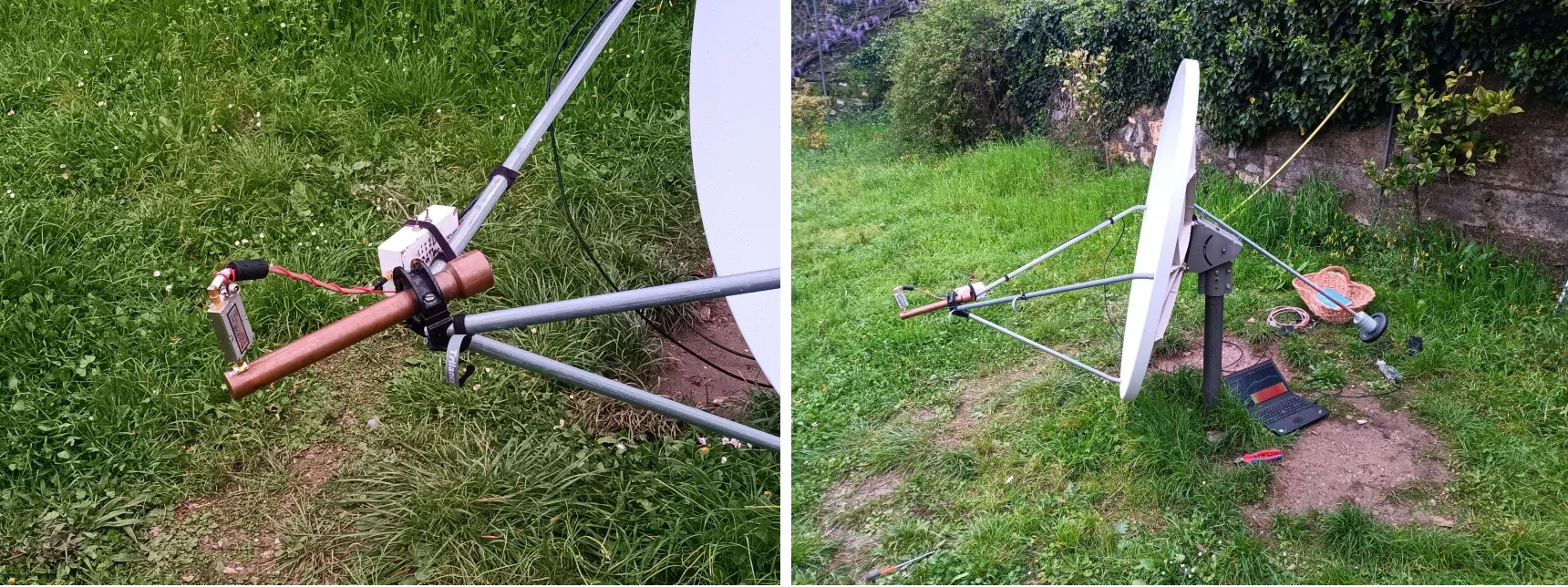
Waveguide feed
The waveguide feed is assembled using common (in Europe - YMMV outside Europe) copper plumbing parts. The waveguide feed has a Teflon depolarizer that can be rotated to switch it from LHCP to RHCP or vice versa.
Materials needed are:
- A 22 cm length of 28 mm copper pipe
- A 28 mm cap
- A panel mount SMA connector with long spill. Good ones are Amphenol (part no. SMA1551E1-3GT50G-50) or Qaxial (part no. SMA04-4H-15).
- A 5 mm thick piece of teflon.
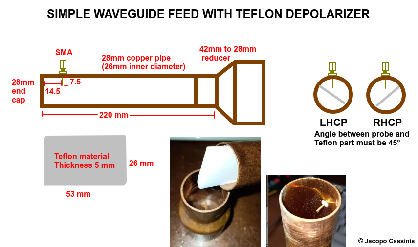
Plans and pictures for a waveguide feed with included offset dish choke (see choke section for more information)
Septum feed
WARNING: the Septum is an advanced feed that, despite the looks, is very hard to build correctly. Therefore, it is NOT recommended to build it as your first X band feed, because it will likely work very poorly. You should rather first build a waveguide feed and get the rest working well, before attempting to build it (unless you manage to find one ready built).
The Septum feed is the best feed that can be used for X band. With very low losses and two separate outputs (one for each polarization) it is ideally suitable for more permanent setups, including automated ones. With two separate LNAs and an RF switch, it is possible to also switch polarization automatically.
I recommend a read of Michael Margaras (SV1CAL)'s website for more information regarding this feed.
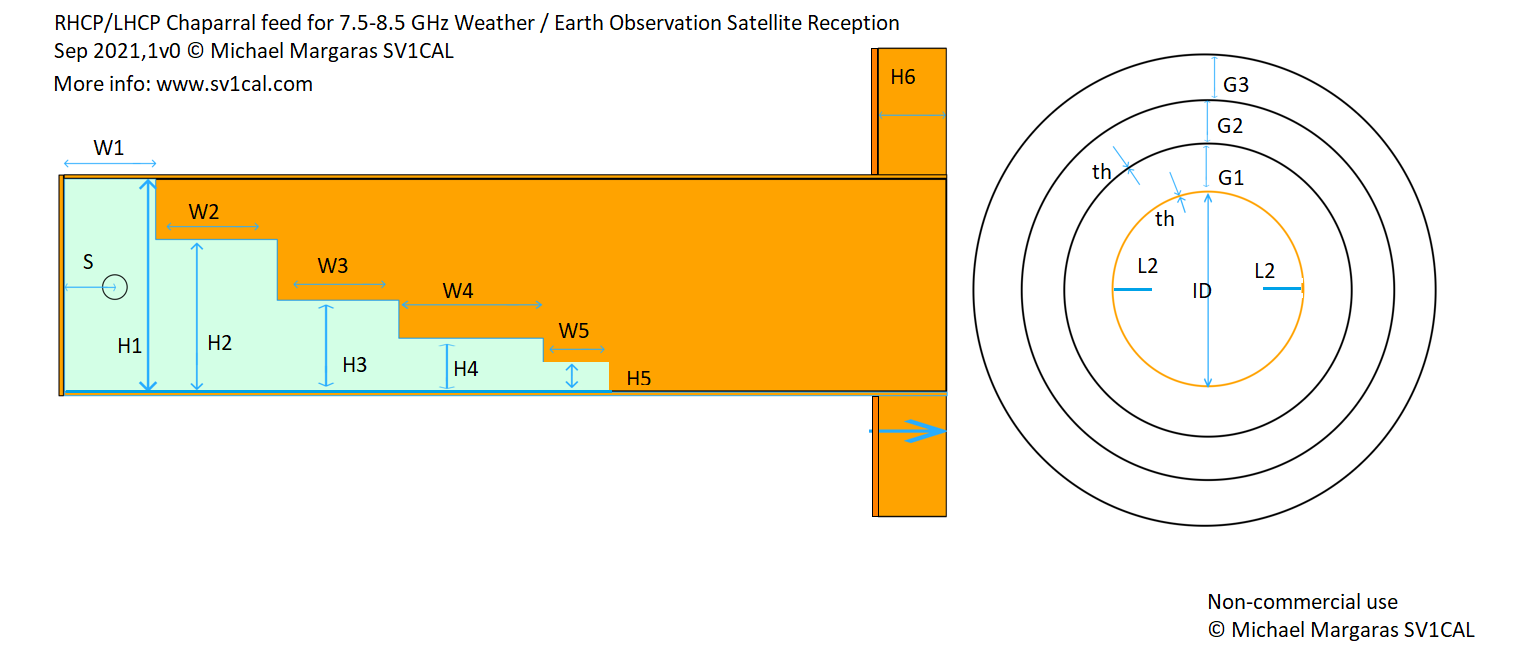
© Michael Margaras. Plans for a Septum feed, the files to be 3D printed as well as other information can be found on his website.
Choke
A choke is essential for proper operation of the feed. An improper or missing choke will cause a SNR hit of several dB.
Offset dishes
For an offset dish if you're using a simple 28 mm pipe waveguide, a good dual mode choke can be made with a 28 mm to 42 mm reducing coupling (also called a reducer). It can just fit at the end of the waveguide.
If you're using the Septum, SV1CAL has a 3D printed choke that can then be electroplated and fits on his feed.
A good document can be found on W1GHZ's microwave website.
Prime focus dishes
For a prime focus, a Chaparral choke is recommended. SV1CAL has a 3D printed Chaparral that can then be electroplated and fits on his Septum feed.
Again, a good document can be found on W1GHZ's website.
Dish mounting
I strongly suggest installing a counterweight (thanks Aang who persuaded me to install it LOL) as it will make hand tracking much easier. It is also important to properly lubricate the mount and ensure it has no bumps while moving and doesn't get stuck or hard to turn throughout the entire angle.
Amplifiers and downconverters
Downconverter
A few practical X band downconverters that can be purchased are the M0KDS downconverter, the Kuhne Electronic GmbH LNC 8085 downconverter and a DS Instruments MX 12000.
The first one is an amateur product and can be obtained from his website. The second one is a professional product, is very expensive and can be found on Kuhne's website. The third one is even more expensive and can be found on DS Instrument's werbsite.
These converters have several LO settings, this is important to avoid the IF falling into LTE/GSM/TV territory and suffering from interference. It is absolutely crucial to avoid the IF getting near the GSM 900 MHz, LTE 800/700 MHz, and TV 600/500/400 MHz bands. A safe band for the IF is around 1 to 1.2 GHz.
Also, the M0KDS converter can't push much power if the IF goes above 1.2-1.3 GHz. Therefore, for satellites like Aqua or Aura, it is recommended to switch to the 7000 or 7600 MHz LO.
If you get the M0KDS converter, I recommend modifying it to add two external switches so you can change the LO on the fly without taking it apart (remember to power down first). This will void warranty, however, so do so at your own risk.
There is also a DIY, but more involved, solution such as described here by Fred Jansen.
The entire setup consists of (from top to bottom):
- A 10 MHz GPS reference signal
- A 6.3 GHz local oscillator from Dieter Leupold
- A 5 GHz high pass filter
- A MACOM M14A double balanced mixer
- To the right, a 2.2 GHz band pass filter feeding the LimeSDR
- Below, a Lotus Microsystems LNA2G18G
- Below, an X band band pass filter.
Naturally, most components can be replaced by others depending on what can be found. Hamfests and conventions are usually good places to score these components for reasonable prices, but sometimes you can get lucky on the Internet as well.
LNA
Finding a suitable LNA is a big hurdle of any X band setup.
Suitable units available for purchase are very expensive, here is a selection of them:
- Down East Microwave, Inc. L4-2ULNA (Approx. $150). Make sure to ask for a retune to the 7.7 to 8 GHz band, unless you're looking for DSN usage exclusively.
- Lotus Communications Systems LNA2G18G (Approx. $200). This is not a very good choice, but it has been used in the past by amateurs.
- Kuhne Electronic GmbH, KU LNA 8000 B (Approx. 480 €). More suited for DSN usage.
- Microwave Amplifiers Ltd, AL-28 (Only quotes). There is a higher gain version available.
Surplus Miteq units command extremely high prices on eBay and the performances are not guaranteed. Sometimes, it is possible to find amplifiers at hamfests, or from fellow hams or at local surplus sales.
The characteristics of a suitable amplifier are summarized below:
- Gain: greater than 20 dB
- Noise: less than 1.5 dB
- Frequency range: 7500 (8000) to 8200.
In general, the overall gain (including the downconverter gain) from LNA input to SDR must exceed about 50 dB.
For LNAs with low gain but low noise floor, such as the DEMI, AL-28 and more, it is very beneficial to add a gain block to help the downconverter. These gain blocks can be had for about 30-70 euros on eBay. They do not need to be low noise, 2-3dB of noise floor are adequate, and the gain can be 20-30 dB.
I'm using an AL-28 amplifier that I got surplus.
SDR
The choice of the SDR depends on the bandwidth of the satellite(s) you want to receive.
A discussion on sample rate and bandwidth.
Ideally, to capture the whole signal with the best SNR, the bandwidth of the SDR would need to be twice as much as the symbol rate of the signal, for example: for a 7.5 M signal (for example, Aqua's DB), you'd want at least 15 Msps on the SDR.
However, as long as the sample rate of the SDR is greater than the symbol rate plus some margin (for Doppler), you can capture the signal as well, just with lower and lower SNR.
You can calculate the oversampling factor by dividing the chosen sample rate by the signal's symbol rate.
For an ideal case, the oversampling factor would be of 2 (for the example above, 15 / 7.5 = 2). The recommended bandwidths in the tables above usually are around 1.4, which is still very safe.
It is not recommended to go below 1.2 as the SNR will be severely impacted.
| Minimum oversampling | Good oversampling | Ideal oversampling |
|---|---|---|
| Invalid input | Invalid input | Invalid input |
SDR choices
These SDRs are the most commonly used when X banding:
- LimeSDR (bandwidth 40 MHz)
- BladeRF xA4 (bandwidth 61.44 MHz, 122.88 MHz with 8 bits, although limited by an 80 MHz filter)
- RFNM (bandwidth 120 MHz, 195 MHz with Granita)
- Aaronia Spectran v6 ECO (bandwidth 61.44 MHz)
- Aaronia Spectran v6 (bandwidth 245 MHz)
- BladeRF x40 (bandwidth 40 MHz)
- LibreSDR B210 mini (bandwidth 61.44 MHz)
- Pluto Plus, AntSDR and other AD9363 Ethernet SDRs (bandwidth 45 MHz reliably)
These SDRs can be used for some satellites:
- MSI.SDR (FengYun-3G only)
- Hydra SDR (FengYun-3G only)
- HackRF (FengYun-3G, SUOMI NPP, AQUA, AURA, NOAA 20 only)
Software and computer
Normally, it is not necessary to think about the computer when setting up a satellite station for other bands, such as the L and S band. Any reasonably modern computer, and sometimes even a Raspberry Pi or cell phone, can handle those.
However, with the X band, it is very important to remember that the high data rates are not only a problem with respect to the choice of the SDR, but also that they have to be somehow written to disk without delays.
Data write rates
Let's take a FengYun-3F as an example. It transmits data at 38.4 M symbols, which means that, according to the 1.5x oversampling rule, the sample rate used should be 57,6 M samples/sec. We'll take 60 to even out.
60M samples/sec at 16 bits per samples (with two equal streams, the I and Q branches) equal to 1920 Mbit/s or 240 MiB/s of data that has to be processed and written to disk. We can reduce the amount by recording at 8 bits per samples, which is what is usually done, and that gives us half the speeds needed for 16 bits: 960 Mbit/s or 120 MiB/s.
Now, you'd probably think any SSD, or even some fast hard disks would be able to handle 120 Mb/s continuous. After all, most modern SSDs are saturating a 6 Gbit/s interface, so what gives?
Writing speeds on storage media
Usually quoted speeds for media are "up to" speeds, that is, achieved under ideal conditions. Next, we have the problem that while copying a file (sequential write) it is not a big deal if the storage media waits a few moments before writing the next block. The file will always be there, none of the data will be lost so a sudden slowdown will just be a minor annoyance.
On the other hand, while receiving a satellite, we need to store the received data without any delay. Even a minor slowdown will cause samples to be lost. With the fast speeds of modern satellite systems, even a few milliseconds worth of data loss will result in an ugly line across the image.
Storage system considerations
It is tempting to buy the fastest, most expensive NVMe drive, but this is not always the right choice for two reasons.
- Consumer NVMe drives are, again, designed to provide fast burst speeds (e.g. when saving a game, or booting the operating system) with no regards for real time writing speeds.
- NVMe relies on a good implementation of PCIe, which means that its performance will depend on the whole I/O system rather heavily.
- NVMe drives are small and tend to overheat rapidly during heavy activity.
SATA drives can perform well, if they're high quality parts. I personally use a Samsung SSD 870 Evo. It's a fairly old part, but it uses triple-level cells rather than the more modern 3D or QLC cells that are less suited to continuous real time writes. I've successfully written up to 50 Ms/s without lost samples on this SSD.
An even better choice would be a SATA or NVMe single level cell (SLC) enterprise drive, of the type used in servers. Unfortunately, these drives are rather hard to find new and expensive, and used solutions are hit-and-miss.
It is usually also better to not use the system drive as the storage drive for X band. This might not always be possible, especially on a laptop, so some settings can be applied to make this possible (with some compromises).
It is always a bad idea to consider using an USB drive for storage, as the USB controller (which is usually a single one, especially on a laptop) will have to share the bandwidth between the two devices, leading to dropped samples.
| Write rate | Space for 1 minute | Space for a pass (15 min) |
|---|---|---|
| Invalid input | Invalid input | Invalid input |
Input/output system considerations
The I/O system used on the motherboard architecture has a heavy impact. Some laptop motherboards are badly designed and heavy I/O loads, especially over USB3 or the PCIe slot will cripple their performance. Depending on the architecture, the USB3 controller can fight for bandwidth with the storage controller (either the NVMe drive itself, or the SATA controller) and this is especially true on older machines.
Usually, desktop computers are better than laptops, but I've always used a Thinkpad X260 with success up to 50 Ms/s with no lost samples.
System memory (RAM) considerations
The satellite reception involves a lot of copying data to and from RAM, and therefore the RAM architecture is important. Single bank, single channel memory can work, provided it is sufficiently fast (2666 MHz DDR4 is usually fast enough in a single bank.)
When more than one bank is present, they must be matched and the dual channel mode must be enabled, otherwise this will result in poor I/O performance and lost samples.
The simple act of removing the second unmatched bank on an old HP Elitebook 820 made it possible to record X band at up to 40 Ms/s, whereas previously samples were being dropped at 15 Ms/s already.
Battery and power management considerations
Laptops have usually power management settings designed to maximize battery life. Unfortunately, this goes against I/O performance, because slowdowns in I/O or latency are hardly noticeable by a normal user.
Therefore, it is best to go in the BIOS setup program and disable all the optimization settings, set "max power" where applicable, and do the same in the operating system.
Usually, it also is necessary to disable power saving for the SATA controller and USB controller.
Operating system considerations
The operating system must share the CPU with many different processes, and this can lead to competition between SatDump and other processes.
Windows is especially prone to this and it is therefore recommended to never use Windows for X band, but rather switch to Linux.
Even on Linux, however, it might be necessary to disable some services especially those that access the disk frequently. On GNOME based distributions, the tracker-miner service is responsible for indexing files. It is best to disable it with systemctl --user mask tracker-store.service tracker-miner-fs.service tracker-miner-rss.service tracker-extract.service tracker-miner-apps.service tracker-writeback.service.
It is also recommended to trim the SSD before each pass with the command sudo fstrim -v /mountpoint (where /mountpoint is the mount point of the SSD in use for recordings). Trimming the SSD reduces the write latency, as each cell is already erased (at neutral potential) and can be written straight away. Without trimming the SSD, the SSD controller must first erase the cell and then write the data, and this can lead to dropped samples.
Satellite reception
Setting the gain
It is very important, especially on the LimeSDR and BladeRF, to set the gain correctly. SatDump has a "magic eye" feature that can help with this.
The "magic eye" is found in the Debug panel under the Recording tab. It needs to be set so that, when the satellite is at the TCA, the "dots" completely fill the "square", but without touching its sides too much.
If the "dots" are grouped together, your gain is too low. If the "dots" are drawing a square, the gain is too high.
Keep in mind that different satellites need different amounts of gain, especially with the M0KDS LNC as the IF exceeds about 1.1-1.2 GHz.
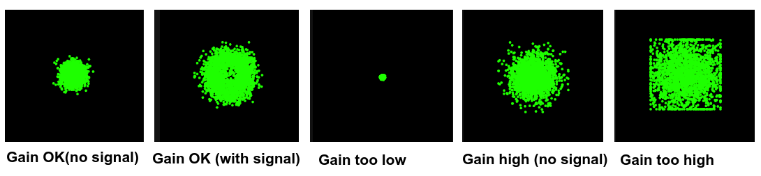
The various aspects of the magic eye. Notice how, with a satellite signal, the magic eye shows a "hole" in the middle or otherwise starts to spin. This is normal.
Manual pointing tips
To successfully point the dish in the X band, the pointing techniques used on the L/S band must be refined further. Even small dish movements, barely noticeable on the L/S band, will have a very large effect on the signal.
A good technique is to "point continuously". On the L/S band you'll be used to "point and wait", but on the X band the position must be adjusted continuously.
It is better to start with low passes, not exceeding 20° in max elevation, and then move to higher and higher elevation passes.
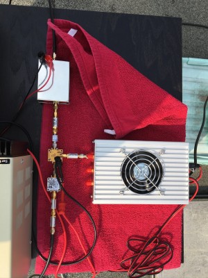
My setup
My setup is fairly bad, but it is enough for some decent receptions.
Hardware:
- 1.2 meters Andrew fiberglass dish
- Waveguide with teflon depolarizer
- Microwave Amplifiers Ltd. AL-28 LNA
- SatDump downconverter (not for sale yet), previously used M0KDS
- BladeRF 2.0 xA4 SDR
- Computers: Fujitsu Lifebook E5412 (up to 265 MHz BW), or Panasonic Toughpad FZ-G1 Mark 4 (up to 50 MHz BW)
The setup is powered via an USB-C (Power Delivery) power bank, and a bias tee. I used a cheap USB-C to 2.1mm barrel plug 12V power delivery cable from Amazon. Naturally, the dish is hand tracked.
Troubleshooting
You'll no doubt run into many problems early in your X band adventure. Here's a list of the most common ones.
Can't see the satellite signal at all
Check the polarization, set the IF frequency correctly in SatDump and to check your jumper or DIP switches settings in the LNC. Test using the telemetry signal from SYRACUSE-3B (LHCP, 7705 MHz, 2 MHz bandwidth).
Signal is very faint and has many nulls or fades
The polarization is wrong. Remember that FengYun-3F and 3H are LHCP.
Signal is very faint, but no nulls or fading
The gain is too low or there is a problem with the hardware (feed or LNA). Adjust the gain using the magic eye. If this happens on Aqua or other satellites in the 8 GHz band, move the LO to a higher settings to have a lower IF.
Spurious signals, pulsing or spiking on the FFT
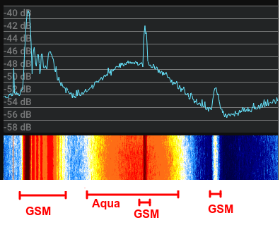
An Aqua signal ruined by GSM interference
There is interference. Switch off or put airplane mode on your cellphone. Change LO to move the IF away from potential interference sources.
Note: it is normal to see thin spikes when using the M0KDS downconverter. They don't affect the reception.
Abnormal constellation while decoding

The most common types of abnormal constellation shapes
- Inverted L: interference with gain too low.
- X shaped: gain too high or SDR overloading
- Offset square: Gain too high with interference
- Donut: frequency wrong, LO wrong, gain slightly high.
- Exploding dot: gain too high or SDR overloading
- Offset dot: interference or gain slightly high
- Squared donut: gain too high or SDR overloading, possibly with a slight frequency offset.
Note: in case of donuts, it is possible to try fixing the situation in two ways. First, the "offset" value needs to be checked, it shouldn't be higher than a few hundred kHz. If it is:
- Decode the signal with an offset of + or - 50kHz (or more).
- In the pipeline settings, half the size of
pll_bwand try again.
Viterbi spikes or deframer desyncing during decoding, with correct constellation
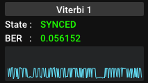
A severe case of Viterbi spiking caused by sample drop
Viterbi spiking is usually caused by either a too low signal, or sample dropping.
This table gives the minimum SNR for a good reception, and can be used to check if it's a sample drop problem or a signal problem.
| Satellite | Minimum SNR |
|---|---|
| SUOMI NPP, NOAA 20 | 6 dB |
| NOAA 21 | 4 dB |
| Aqua, Aura | 11 dB |
| FengYun-3 D, E, F, G | 7 dB |
Sample drop problems (that didn't use to be there)
Sample drop problems can be cured with the following methods:
- Reboot the computer and close every program, including the ones in the tray bar.
- Set the power plan to "full power" or "max power".
- Give SatDump maximum priority from the task manager
- Ensure the computer is not overheating
- Disable power management for SATA, USB and PCIe
- Trim the SSD.
Reed-Solomon stuck on all red blocks, but signal is high enough
The gain is too high. Reduce the gain.
With every gain setting, the constellation is abnormal or the SNR is very low.
The SDR might be overloading. Use a longer cable, of lower quality even (such as cheap RG58 from Amazon), or an attenuator.
M0KDS downconverter cuts out
The 7805 regulator inside might be overheating. Check the temperature. Also, there might not be enough voltage getting to the 7805. Check the voltage at the downconverter.
M0KDS downconverter makes a squealing noise
The voltage getting to the LNC is insufficient.
Terra has no signal
Terra's DB has been permanently switched off since September 2024 due to solar array faults that were causing the satellite to safe mode and reboot spontaneously.
FengYun-3G has no signal
Due to the low orbit of FengYun-3G, it needs to be periodically reboosted using onboard propulsion to combat orbital decay caused by friction with the atmosphere. When this operation is carried out (usually every month or so) the satellite will not transmit any data on X band.
Have fun with X band!